Description of the tools for modelling and prototyping
There are several types of tools used to design models and prototypes. Below is a list, in chronological order of use, in the different steps of prototyping:
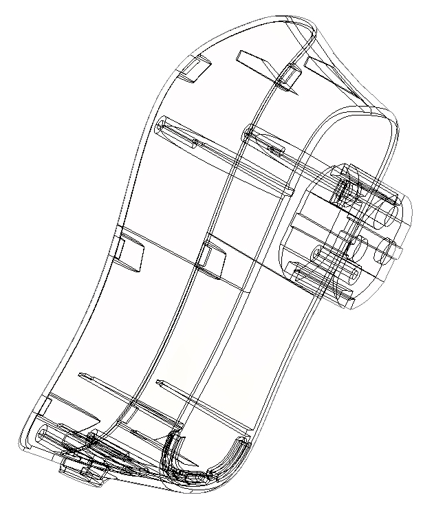
– Plans: these are 2D files or 3D files. The latter are a three-dimensional computer representation of the part. They show data such as geometry, dimensions, tolerances, diameters, possible standards, specifications, and materials, etc.
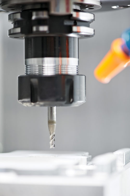
– Machines: all prototyping techniques require the use of machines. These are machining centers for CNC, 3D printers for additive techniques and machines with depressurized chambers for silicone molding.
– Machine accessories: the machines described above use components that influence production. These are CNC nozzles and milling machines, vacuum casting ovens or UV laser for polymerization of resins in 3D printing and stereolithography.
– Tooling: vacuum duplication requires a master part and a silicone mold.
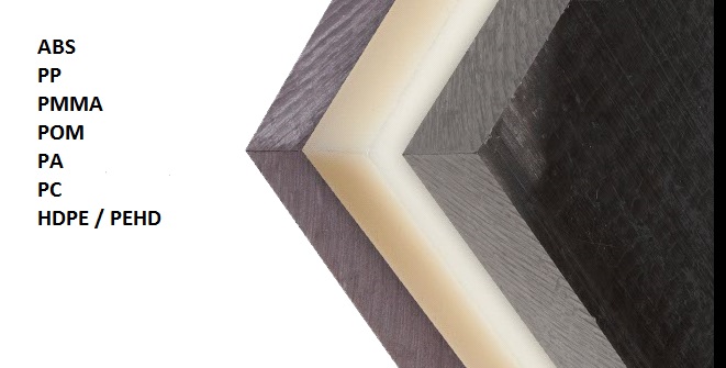
– Materials: the plastic and metal materials differ from one technology to another. The production is performed with a block of plastic material, a resin or a polyurethane for the parts and with a type of silicone for the molds.
– The material used for post-production surface treatments: these are generally used in manual manipulations to apply finishes. It is gloss paint for a polished-glossy finish, a specific paint for a soft touch effect, a dye for a mass color rendering, various tools and products (gun, etc.) for sandblasting, galvanizing, electroplating and polishing of the surfaces of the parts.
– Quality control tools: Once the manufacturing is complete, devices are used to verify the conformity of the parts with the customer’s specifications. These include, for example, durometers to ascertain the hardness of flexible parts (by measuring the degrees of shore), or even calipers to check the dimensions and diameters.


